





BIM Structural Steel Detailing, Node Optimization & Shop Drawings
Our in-house detailing team turns your design drawings into a Tekla Structures model, checked connections, shop drawings, NC files and a weight-accurate BOM. First issue in 5–10 working days.
One model drives drawings, CNC and the BOM
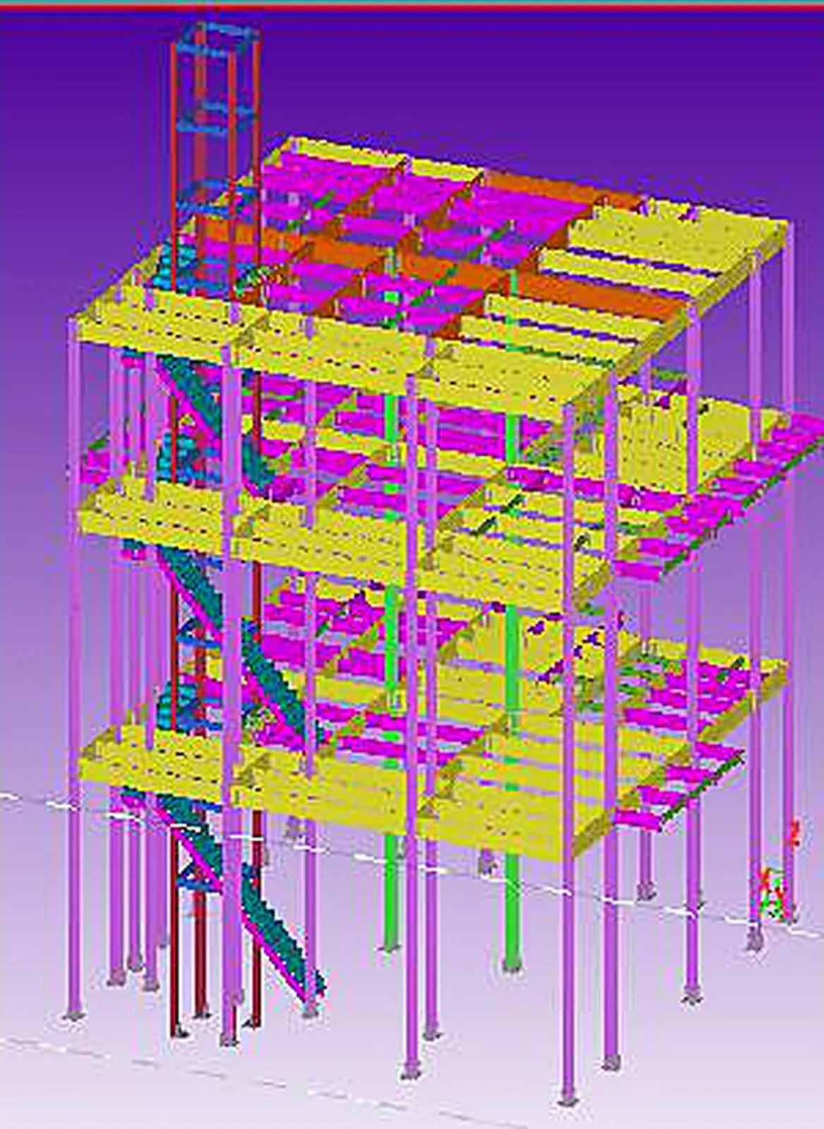
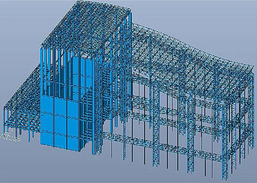
Detailing is where a design becomes a buildable steel package. We model every member, plate, bolt and weld in Tekla Structures, then generate drawings and machine files straight from the model. Nothing is redrawn by hand, so the drawing, the NC file and the weight on the BOM always agree.
The team works on box columns, plate girders, pipe and box trusses, multi-cavity mega columns and secondary steel. Typical packages run from 50 t mezzanines to towers above 18,000 t. For complex nodes we model weld access, bevel types and assembly sequence, because a node that cannot be welded in the shop will not be welded on site either.
- Input: IFC, DWG, DXF, PDF, Revit export or Tekla model
- Connection design to AISC 360, EN 1993-1-8 or AS 4100
- Clash check against architectural and MEP models when supplied
- BOM accuracy within 2% of final shipped weight
LOD 300 to LOD 400, matched to the stage
We agree the LOD at kick-off so the model carries enough detail for its next user and no more.
| Level | What is modelled | Typical use |
|---|---|---|
| LOD 300 | Members at correct size, grade and position. No connection plates. | Tender take-off, early BOM, design coordination |
| LOD 350 | Connections, base plates, splices, stiffeners and embeds positioned | Clash check with MEP and facade, RFIs |
| LOD 400 | Every plate, bolt, weld, bevel, hole and camber. Assembly marks. | Shop drawings, NC files, fabrication and erection |
| LOD 500 (as-built) | Model updated with approved site changes and survey data | Handover to owner, facility management |
Default scope is LOD 400 for fabrication. LOD 300 models are issued free with tender BOMs for projects we quote.
What the detailing package contains
General arrangement drawings
Plans, elevations and sections with erection marks, grid lines and setting-out levels.
Assembly drawings
One sheet per shipping piece: dimensions, welds, bolts, camber and paint zones.
Single-part drawings
Plates and profiles with holes, bevels and cut-outs for the workshop.
NC / DSTV files
NC1 files for drilling, sawing and plasma lines. DXF nesting for plate cutting.
BOM and weight report
Tonnage by member type, grade and area. Bolt and stud lists. Paint surface area.
Connection calculations
Bolt and weld checks for typical and special connections, with design forces stated.
Clash report and RFI log
Clashes, design gaps and questions listed with screenshots and proposed answers.
IFC model
Coordination model for your BIM manager, viewable in Navisworks, Solibri or Trimble Connect.
From design drawings to approved shop drawings
A 300–800 t package typically reaches approval within three weeks. Larger projects are split into areas or sequences so fabrication can start on the first area while the rest is still being detailed.
Approval of shop drawings starts the fabrication clock: 25–40 days for standard members, 40–60 days for complex multi-cavity and twisted members.
-
D1
Kick-off and design review
Codes, grades, loads and connection design responsibility confirmed. LOD and drawing standard agreed.
-
D2–3
RFI list issued
Missing dimensions, unclear connections and design conflicts raised in one log, not one email at a time.
-
D3–7
Modelling and connection design
Members, connections and embeds modelled. Clash check run against supplied models.
-
D8–10
First issue for approval
GA, assembly drawings and connection calcs issued as PDF plus IFC.
-
+3–5 d
Client comments closed
Comments returned in a marked-up PDF are incorporated and re-issued within 2–3 working days.
-
Approved
Issued for construction
NC files released to the workshop. Fabrication lead time starts.
We read what your consultant issues
If your design team works in Revit, SAP2000, ETABS, STAAD or Robot, send the drawings and an IFC export. Analysis results help us size connections.
| Format | Direction | Used for |
|---|---|---|
| IFC 2×3 / IFC4 | In and out | Design model import, coordination model export |
| Tekla (.tsep, model folder) | In and out | Native exchange with Tekla users, model handover |
| DWG / DXF | In and out | Design drawings, GA drawings, plate nesting |
| In and out | Design drawings, shop drawing approval, mark-ups | |
| NC1 (DSTV) | Out | CNC drilling, sawing and coping lines |
| KSS / CSV / XLSX | Out | BOM, MIS import, bolt and paint lists |
| Revit (via IFC) | In | Architectural and MEP coordination |
What a typical package looks like
Want to see the sheet layout before you send drawings? Download our sample set.
| Project type | Tonnage | Drawing sheets (approx.) | First issue |
|---|---|---|---|
| Single-storey PEB warehouse, 30 m span | 300 t | 120–180 | 5 working days |
| Multi-storey logistics building | 1,500 t | 600–900 | 8–10 working days, by zone |
| Long-span pipe truss roof, 74 m | 800 t | 400–600 | 10 working days |
| High-rise core and frame, mega columns | 7,000 t+ | 3,000+ | Staged by floors, 10 days per stage |
| Skybridge or link bridge | 200–700 t | 150–300 | 7 working days |
Indicative values from past packages. Actual sheet count depends on repetition and drawing standard.
Connections designed for the workshop and the crane
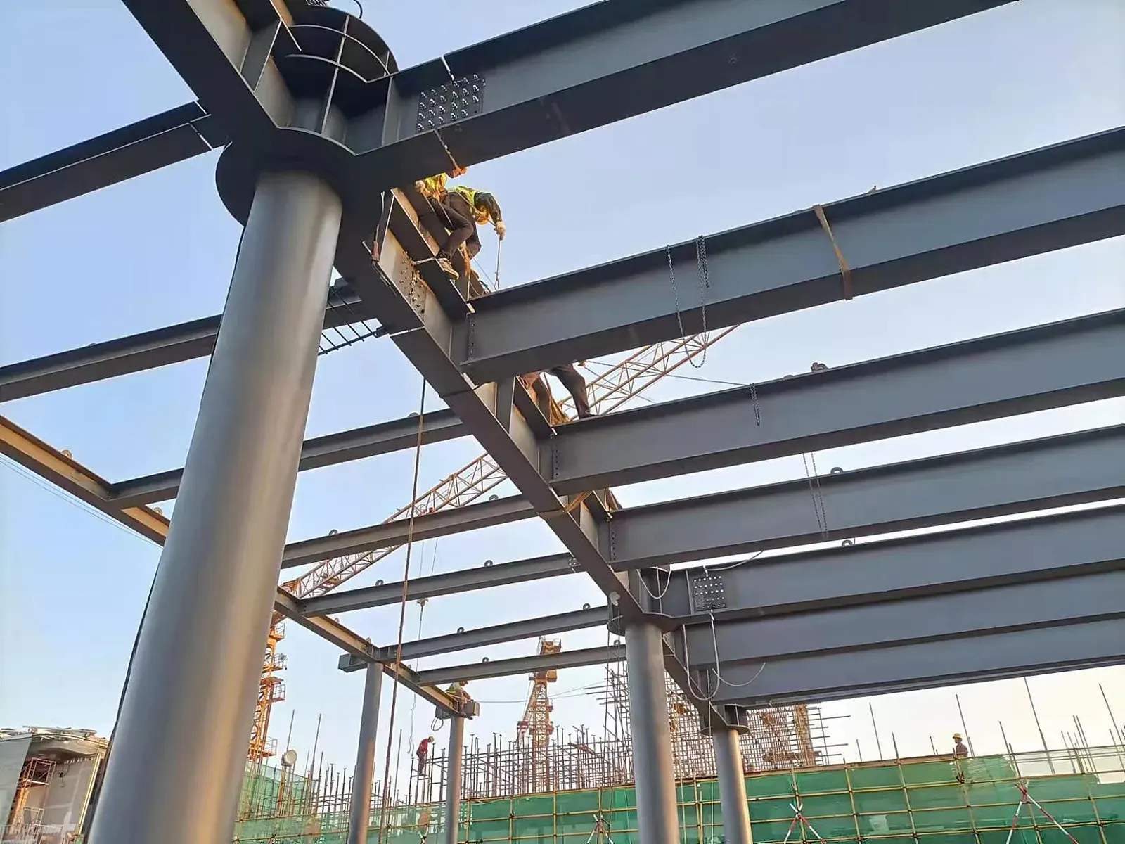
Connections drive cost more than tonnage does. A moment connection with full-penetration flange welds costs several times a bolted end plate. During detailing we propose alternatives where the design allows, and we flag where it does not.
- Standardise bolt sizes and plate thicknesses to cut variety on site
- Move welds to the shop and bolts to the field where possible
- Size splices for 11.8 m containers or the agreed crane capacity
- Check weld access and sequence on multi-cavity mega columns
- Camber and pre-set on long-span trusses and transfer girders
On the CGN Headquarters, multi-cavity column nodes were modelled with weld sequence and inspection access before release. See our complex nodes and box column pages for processing limits.
Detailing questions
Next step after approval: fabrication, coating and testing. See coating and fireproofing and quality, NDT and shipping.
How much does steel detailing cost?
Detailing is usually priced per tonne of modelled steel, roughly USD 25–60/t depending on complexity. When we also fabricate the steel, detailing is included in the fabrication price.
Who is responsible for connection design?
This is agreed at kick-off. We can design connections to AISC 360, EN 1993-1-8 or AS 4100 using your design forces, or detail connections already designed by your engineer of record.
Can you work from PDF drawings only?
Yes. PDF design drawings are enough for modelling. An IFC or analysis model shortens the RFI stage, because member positions and forces can be read directly.
How do you handle design changes?
Changes are logged with a revision cloud and revision letter. The model, drawings, NC files and BOM are updated together, and the change log shows the tonnage impact.
Will I receive the Tekla model?
Yes. The IFC model is part of every package. The native Tekla model can be handed over at project end on request.
Send your drawings. Get a 24-hour BOM and FOB price.
DWG, IFC, Tekla or PDF. Engineering review by our Tekla team, from 50 t or 2,000 m².