CGN Headquarters High-Rise: 18,472 t of Steel for Three Towers
Box SRC mega columns, H-section SRC beams and a concrete-filled tube podium frame for the China General Nuclear headquarters in Longgang, Shenzhen. Fabricated in Guangdong for CSCEC 8th Bureau, 2018–2021.
A headquarters campus built around steel
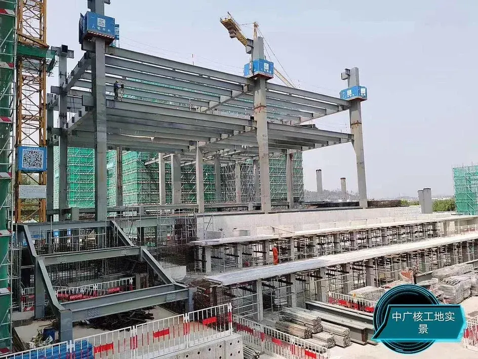
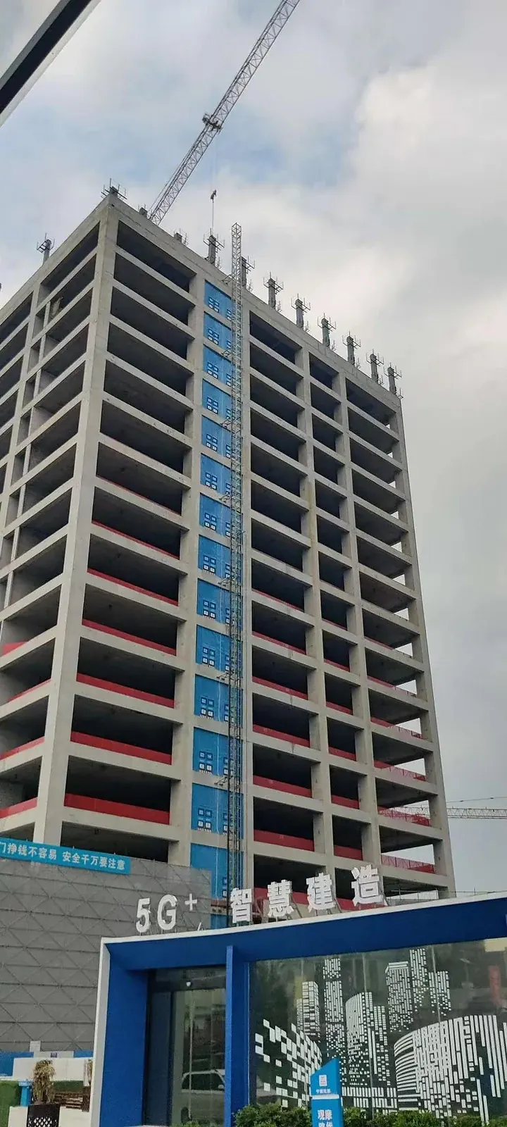
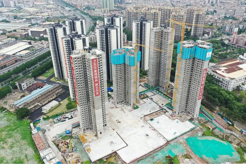
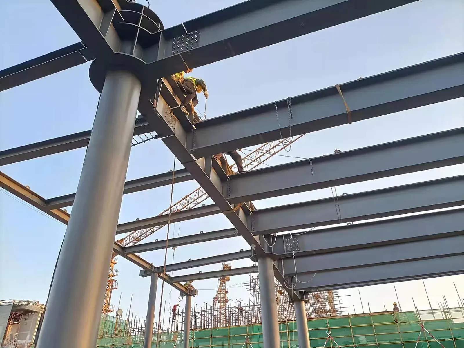
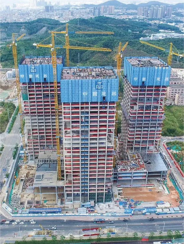
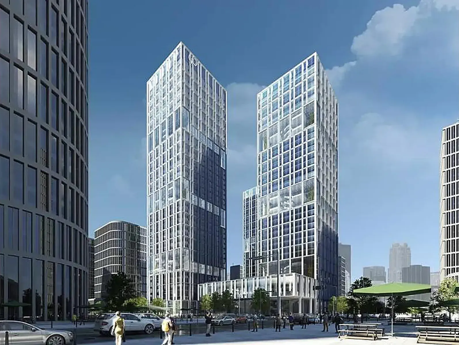
The CGN Engineering Building is the headquarters campus of China General Nuclear Power Group in the Baolong new-energy district of Longgang. Towers A, B and C and the connecting podium all use structural steel. The tower perimeter frames are steel-reinforced concrete (SRC): welded box columns and H-section beams encased in concrete. The podium is a concrete-filled steel tube (CFST) column and steel beam frame.
Guiguan detailed, fabricated, coated and delivered the steel package to the main contractor, CSCEC 8th Bureau, and provided erection supervision on site.
| Item | Detail |
|---|---|
| Owner | China General Nuclear Power Group (CGN) |
| Main contractor | China State Construction 8th Engineering Division |
| Location | Baolong new-energy base, Longgang District, Shenzhen |
| Building type | Headquarters office towers A/B/C with retail and conference podium |
| Site / GFA | 26,800 m² site · 328,900 m² GFA |
| Structural steel | 18,472 t |
| Key members | Box SRC columns, multi-cavity columns at transfer levels, H-section SRC beams, CFST podium columns, truss floor deck |
| Steel grades | Q355B/C for beams and podium; Q420GJC for thick column plate |
| Plate thickness | 16–60 mm typical, column plate to 60 mm |
| Our scope | Tekla detailing, fabrication, blasting and coating, delivery, erection supervision |
| Program | Start 2018 · topped out December 2021 |
Tonnage and member data from fabrication records; areas and dates from the owner and main contractor.
Heavy columns, dense rebar, a fixed topping-out date
SRC towers combine the tolerance demands of steel with the congestion of reinforced concrete. Every column passes through rebar cages at every floor.
Thick-plate box columns
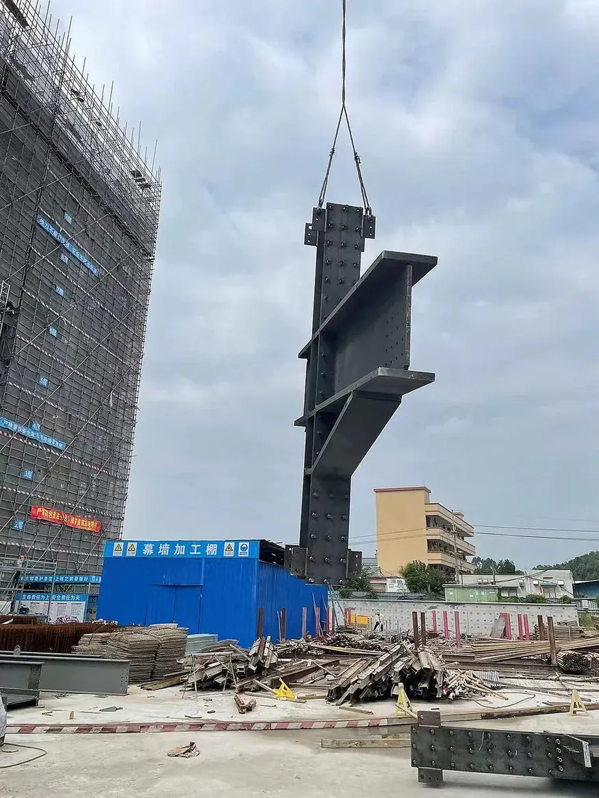
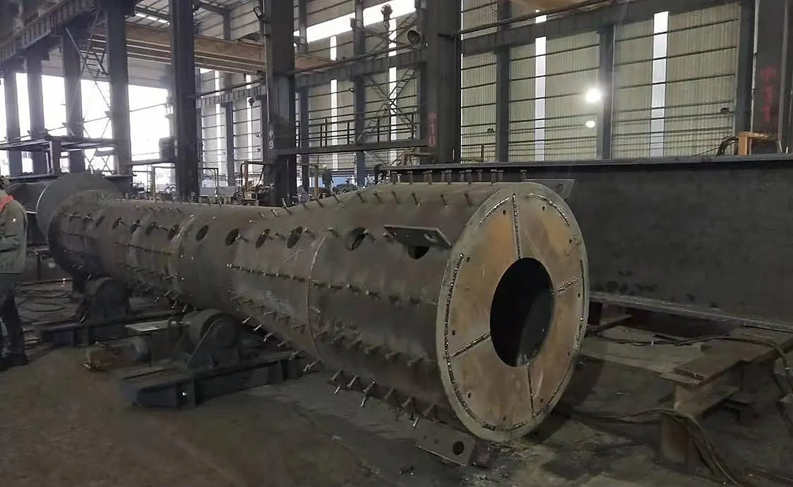
Column segments up to about 25 t with 40–60 mm Q420GJC plate. Lamellar tearing and preheat control at corner welds were the first fabrication risk.
Rebar congestion at joints
Beam flanges, column diaphragms and vertical bars meet at each node. Every rebar hole, coupler and stud had to be placed in the shop, not drilled on site.
Three towers, one crane plan
Towers A, B and C rose in parallel. Column segments had to arrive in lift sequence, one to two floors ahead of the concrete pour.
Mixed systems
SRC towers, a CFST podium and truss floor deck had to tie into one model with consistent erection marks.
Verticality
Column verticality held within H/1000 and 15 mm overall to keep cladding brackets and lift shafts true.
Weld volume
Full-penetration welds on every column splice and diaphragm. 100% UT was specified for all CJP joints.
One Tekla model for towers and podium
We built a single Tekla Structures model covering the three towers, the podium and the floor deck interfaces. Column splices were set about 1.3 m above floor level, three storeys per segment, to suit crane capacity and keep site welding at a workable height.
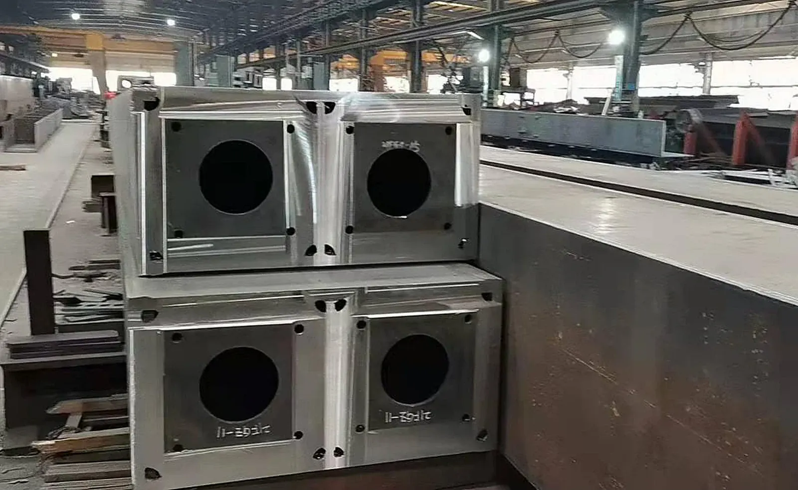
Inside each box column, internal diaphragms at beam flange levels were welded by electroslag welding (ESW) through access holes. Concrete pouring holes and vent holes were cut in each diaphragm. Rebar couplers and through-holes were coordinated with the RC designer in the model and released in the shop drawings, so the site crew never cut steel.
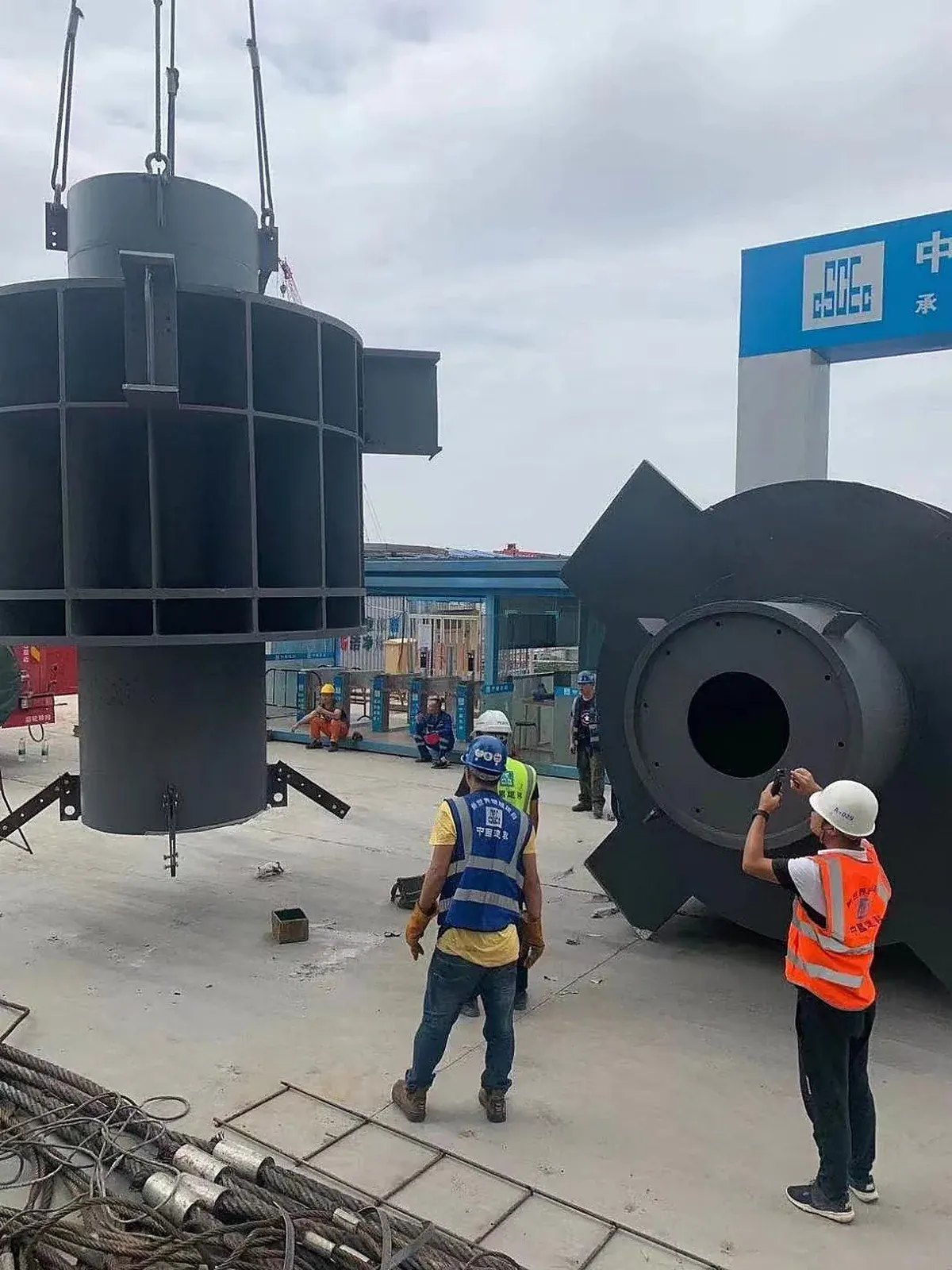
At transfer levels the columns change to multi-cavity sections. These were assembled cell by cell with sequence-controlled welding to limit distortion.
| Member / detail | Section & grade | Detailing note |
|---|---|---|
| Tower SRC column | Welded box 800×800 to 1,200×1,200, t = 30–60 mm, Q420GJC / Q355C | ESW internal diaphragms, pour and vent holes, shear studs |
| Transfer column | Multi-cavity box, 3–4 cells, Q420GJC | Cell-by-cell assembly, trial-fitted with beam stubs |
| SRC beam | Welded H 600–1,000 deep, Q355B | Rebar holes and couplers placed in shop |
| Podium CFST column | Circular tube Φ600–1,000, Q355B | Internal ring stiffeners, concrete pumped from below |
| Floor beams | Rolled and welded H, Q355B | Bolted shear tab, slip-critical 10.9S bolts |
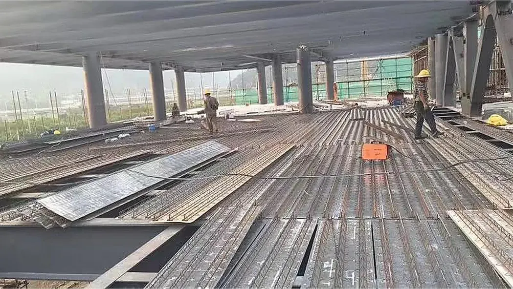
| Floor system | Truss floor deck, 1.2 mm base | No props, studs welded through deck |
Thick plate, controlled heat, recorded welds
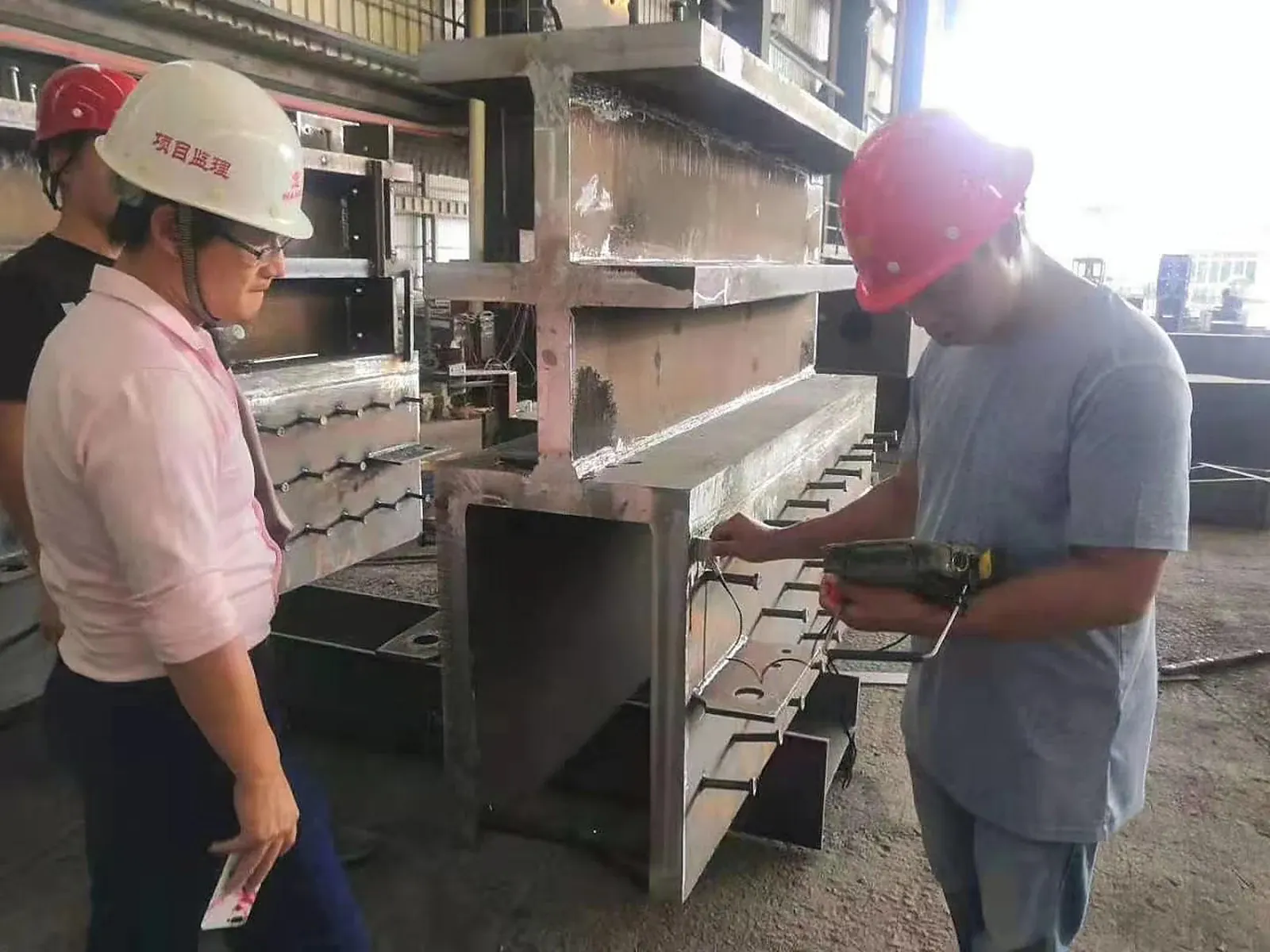
Q420GJC plate was ordered with Z25 through-thickness properties for column corners. Every heat came with an EN 10204 3.1-equivalent MTC, traced to piece marks. Corner and splice welds used submerged-arc welding with preheat of 80–120 °C on plate over 40 mm, with interpass temperature logged.
Each column segment was surveyed for length, twist and end squareness before blasting to Sa2.5 and priming.
- 100% UT on CJP welds; MT on fillet welds by sampling
- Z25 plate for lamellar tearing resistance
- Dimensional report per column segment
- Trial fit of transfer columns with beam stubs
- Primer DFT recorded per piece
Columns arrived in lift order, floor by floor
The erection sequence was planned in the model and fed back into the fabrication schedule.
-
01
Detailing, 2018
Tekla model, connection review with the designer, rebar coordination and phased shop drawing release.
-
02
Basement and podium
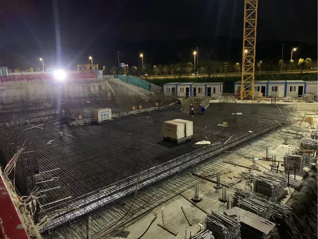
Embedded column bases and CFST podium columns delivered first; anchor templates checked by survey.
-
03
Tower cycles
Three-storey column segments delivered in lift order, typically one to two floors ahead of the concrete core.
-
04
Splice welding and UT
Site splices welded with preheat and tested by UT before concrete encasement.
-
05
Transfer levels
Multi-cavity columns erected after trial fit in the shop; no site rework recorded.
-
06
Topping out, Dec 2021
Main structure of all towers topped out; steel package closed with as-built records.
18,472 t delivered to a fixed topping-out date
The steel package was delivered in sequence for three towers running in parallel. Rebar coordination done in the model meant column holes and couplers matched the cages at each floor. Transfer-level multi-cavity columns went up without site modification after shop trial fitting.
The same approach applies to export high-rise work: a single model, plate traceability, ESW diaphragms and splice-level QC records that a consultant can audit. See multi-cavity nodes and high-rise steel.
Systems and members used on this project
Each page lists spans, grades and processing limits. See all reference projects.
Questions about this project
Planning a similar structure? Send drawings and our engineers reply within 24 hours.
What was Guiguan's scope on CGN Headquarters?
Tekla detailing, fabrication of 18,472 t of structural steel, blasting and coating, delivery in erection sequence and erection supervision. Erection was by the main contractor, CSCEC 8th Bureau.
Why use SRC columns instead of plain steel?
SRC combines steel capacity with concrete stiffness and fire protection. It reduces column size versus RC and avoids heavy fireproofing versus bare steel, which suits tall office towers.
How thick was the column plate?
Typical 30–60 mm, in Q420GJC for the heaviest columns with Z25 through-thickness properties. Our shop handles plate up to 100 mm.
Can you supply similar columns for export?
Yes. We detail to AISC 360, EN 1993 or AS 4100, supply S355J2 or A572 Gr.50 equivalents, and ship segments up to 24 m and 60 t break-bulk or cut to suit 40HQ containers.
How long does a high-rise column package take?
Shop drawings take 5–10 working days per release. Fabrication runs 25–40 days after approval, or 40–60 days for multi-cavity columns, with deliveries phased to the floor cycle.
Send your drawings. Get a 24-hour BOM and FOB price.
DWG, IFC, Tekla or PDF. Engineering review by our Tekla team, from 50 t or 2,000 m².