





Q420GJC thick plate3D scan verificationShop trial assembly
Custom Multi-Cavity Mega Columns, Y/X Nodes & Twisted Steel Fabrication
Multi-cell mega columns, cruciform columns, Y/X branch nodes and twisted box members for super high-rise and free-form buildings. 3D modeled, sequence-welded in thick plate, scanned and trial-assembled before shipment.
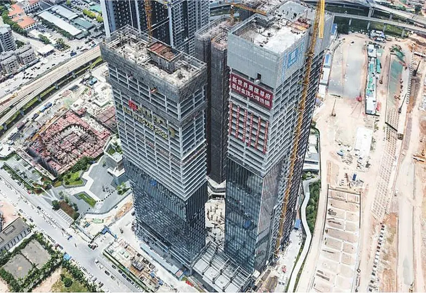
18,472 tCGN HQ steel, incl. mega columns
241 mZengcheng tower, Q420GJC
≤ 100 mmPlate thickness
40–60 daysLead time
01Engineering definition
The members that cannot be bought, only built
Multi-cavity columns and branch nodes appear where loads are highest and geometry is least regular: the perimeter of super high-rise towers, transfer levels, tree columns and free-form roofs. They are custom heavy weldments, priced by complexity rather than by tonne.
What makes them hard is access and distortion. A four-cell column has internal webs that must be welded and tested before the outer plates close them. A node with six branches moves as it cools. We plan both in the model: fabrication steps, weld sequence, distortion allowances and inspection points, before any plate is cut.
The result is a piece that fits the steel around it on the first lift. That was the requirement on the CGN Headquarters and the Zengcheng New World tower.
- 日, 目, 田, E and 王 multi-cell sections
- Cruciform, Y and X nodes, twisted box members
- Welded alternative to cast steel nodes
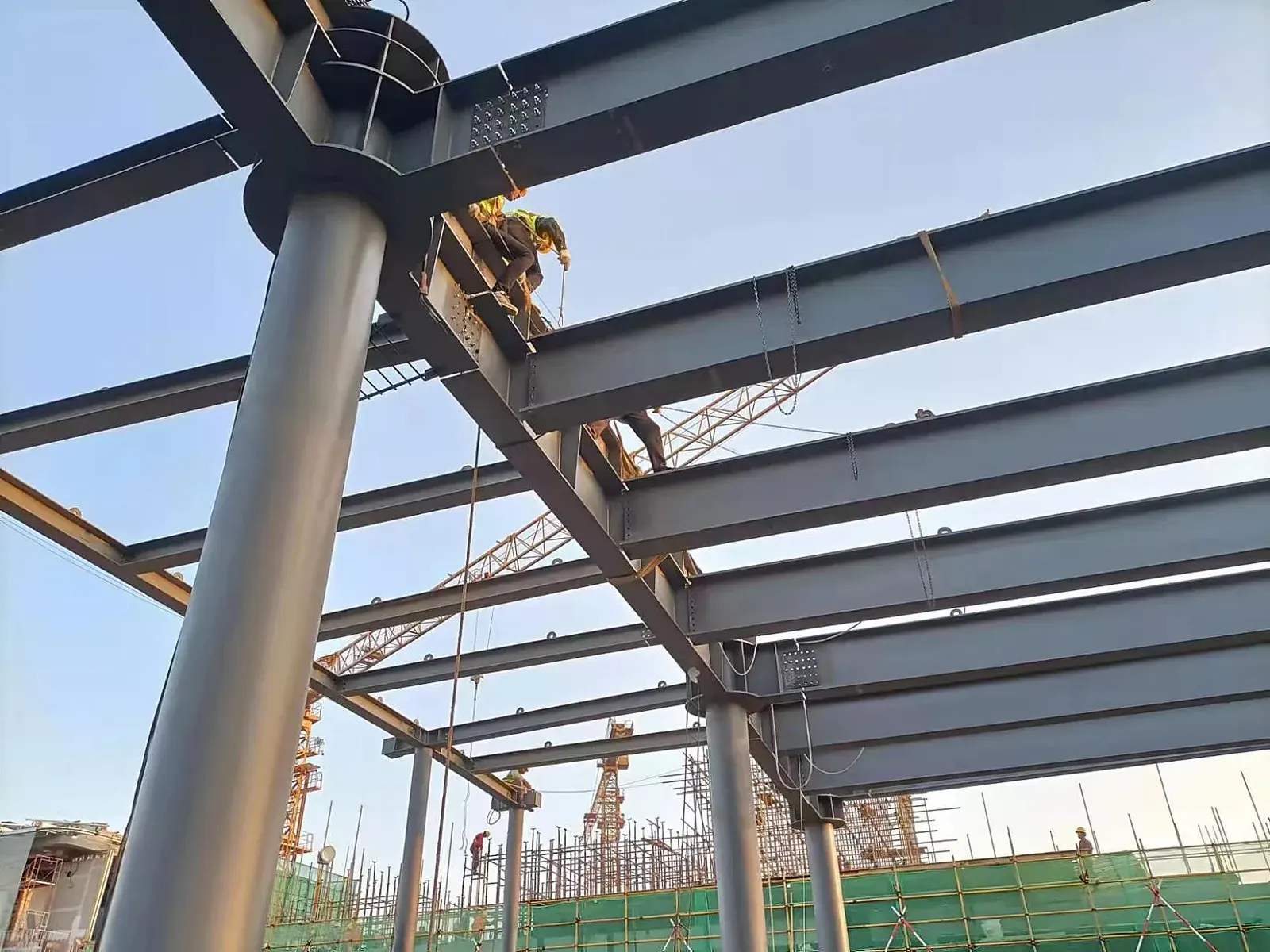
Heavy beam-column connection node
02Section types
Four families of complex members
Select a family to see how it is made and where it is used.
Multi-cell sections for super high-rise frames
Mega columns combine several boxes into one section: two cells (日), three cells (目), four cells (田) or E and 王 shapes with internal webs. They carry gravity and overturning loads in the perimeter of towers above 200 m. Sections over 3,000 mm are built in segments with welded field joints.
- Two to six cells per section
- Internal webs welded by SAW and ESW in sequence
- Concrete filling and vent holes per cell
Steel cores for SRC columns and wall junctions
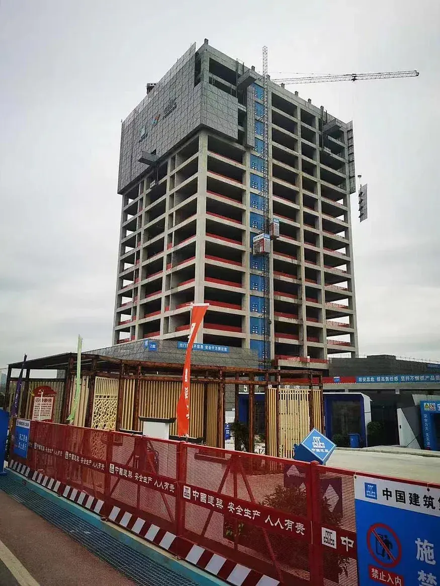
Cruciform (+) columns are built from an H and two T-sections, or from plate. They sit inside steel-reinforced concrete columns and wall junctions where beams frame in from four directions.
- Rebar holes and couplers positioned from the model
- Shear studs welded in the shop
- Stiffener layout coordinated with reinforcement
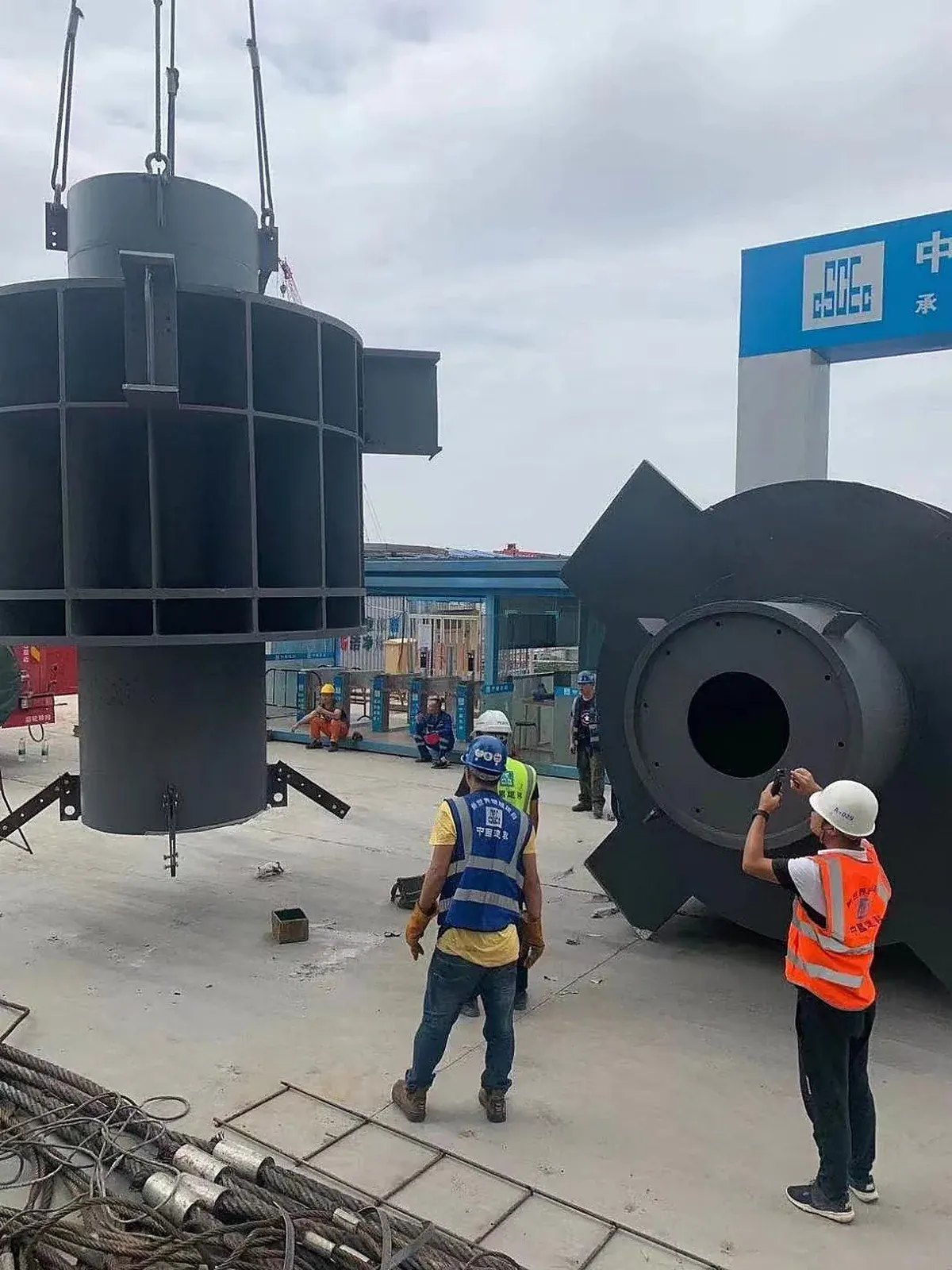
Welded nodes where many members meet
Branching columns, tree supports and truss nodes bring three to eight members together at different angles. We build them from plate and tube as a single welded piece, so the site only makes simple butt joints to each branch.
- Branch angles taken from 3D work points
- Internal stiffeners for force transfer
- Alternative to cast steel nodes at lower cost
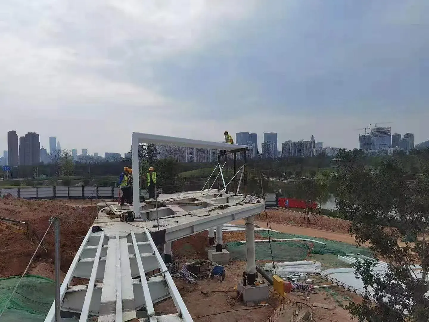
Doubly curved box members for free-form architecture
Twisted rectangular box members follow a curve in plan and elevation while the section rotates. Each plate is unfolded from the 3D surface, CNC cut, pressed to shape and welded on a 3D jig with surveyed control points.
- Plate unfolding from the Tekla or Rhino model
- Jig control points every 1–2 m
- Final shape verified by 3D scanning
03Dimensional & processing limits
Complex member limits
Typical values. Each node is reviewed for weld access and transport before quotation.
| Item | Limit | Note |
|---|---|---|
| Multi-cavity section | Segments up to 1,800 × 1,800 mm; full section beyond 3,000 mm | Assembled from segments with welded field joints |
| Plate thickness | 12–100 mm | Q355GJ / Q420GJC with Z15–Z35 testing |
| Single piece length | ≤ 24 m | Mega columns typically one or two floors per piece |
| Single piece weight | ≤ 60 t | Set by site crane capacity |
| Node branches | 3–8 members per node | Angles to the model, any direction |
| Work point tolerance | ±3 mm | Branch end positions after welding |
| Twisted member profile | ±3 mm to the 3D surface | Checked by 3D scan against the model |
| Lead time | 40–60 days | After shop drawing approval |
Complex members are quoted from drawings, not by standard tonnage price.
Plant limits that apply
| Item | Capability |
|---|---|
| Welded box columns & beams | 300 × 300 to 1,800 × 1,800 mm; plate 12–100 mm (multi-cavity mega columns in segments beyond 3,000 mm) |
| Steel grades | Q235B–Q460, Q355GJ, Q420GJC; ASTM A36 / A572 Gr.50 / A992; EN S235–S355J2 / NH |
| Max. piece length | ≤ 24 m in the shop; ≤ 11.8 m for 40HQ containers; full length by break-bulk |
| Max. piece weight | ≤ 60 t (workshop crane capacity) |
| Welding processes | SAW, GMAW (CO₂), electroslag (ESW), robotic welding |
| Inspection | 100% UT on all full-penetration welds; MT/PT per AWS D1.1 / GB 50205; EN 10204 3.1 MTC |
Typical values. Final limits are confirmed per project in our quotation.
Full plant limits for every member family are in the capability table.
04Materials & welding
Building-structure steels and planned welding
Complex members almost always use thick plate. We specify Q355GJ or Q420GJC (GB/T 19879), building-structure steels with controlled yield ratio, narrow strength range and through-thickness (Z-direction) properties. The Zengcheng New World 241 m tower used about 7,000 t of Q420GJC. EN or ASTM grades with equivalent properties can be supplied when the engineer of record specifies them.
The welding sequence is planned before cutting. Each node has a written sequence, preheat and interpass limits, and planned distortion allowances. Joints that will be enclosed are welded and tested before the next plate closes them.
| Joint | Process | Test |
|---|---|---|
| Cell skin and internal webs | SAW / GMAW | UT 100% (CJP) |
| Diaphragms inside cells | ESW | UT 100% |
| Branch-to-node | GMAW (CO₂), multi-pass | UT 100% |
| Thick-plate T-joints | Preheat + post-heat | UT 100%, lamination check |
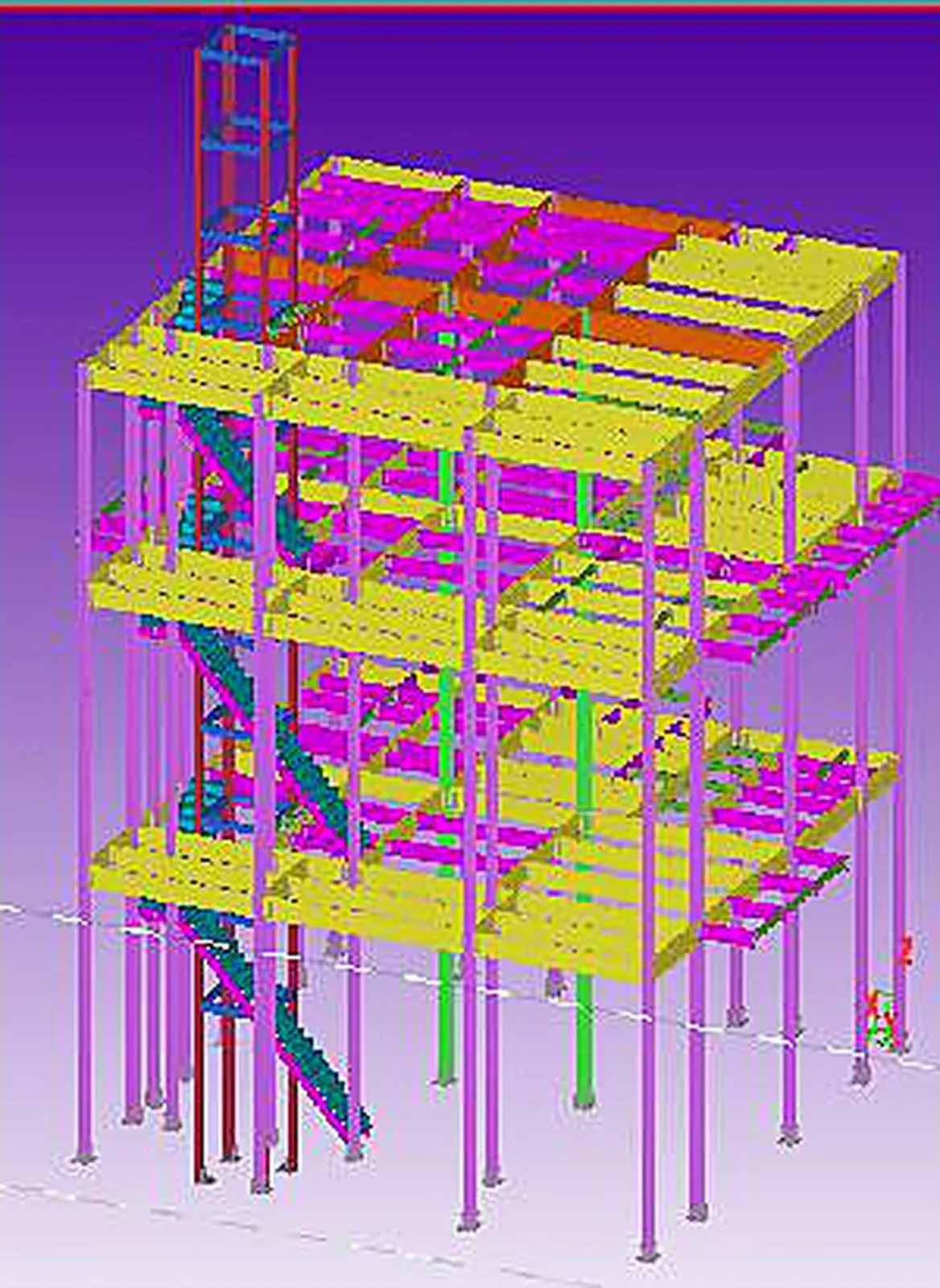
3D model used to sequence node fabrication
05Quality control
Controls for members that must fit first time
Every complex member ships with weld maps, UT records and survey data.
3D model first
Every node is modeled, checked for weld access and split into fabrication steps before plate is ordered.
Sequence-controlled welding
Written weld sequence per node; each enclosed joint tested before closure.
3D scan and survey
Work points and surfaces checked against the model; deviations reported per piece.
Trial assembly
Adjacent mega column segments and nodes fitted in the yard and match-marked.
Related services
Sa2.5 blasting, epoxy zinc-rich systems, hot-dip galvanizing and intumescent coating.
100% UT on CJP welds, dimensional reports, MTC 3.1, packing and port logistics.
06Applications
Where this member family is used
Building systems where this member family does most of the work.
Mega columns, outrigger nodes and transfer joints for towers above 150 m.
07Reference project
CGN Headquarters, Shenzhen
The CGN Headquarters tower frame used multi-cavity mega columns and heavy outrigger trusses, part of 18,472 t of steel we fabricated for the project. Column segments were trial-fitted in the shop, surveyed and delivered in lift sequence.
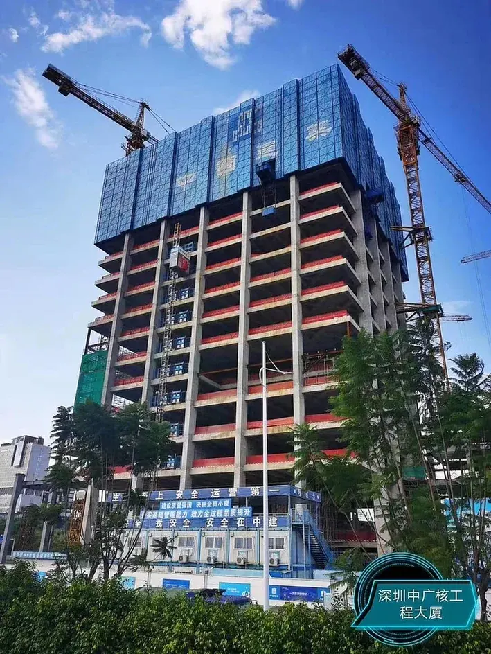
For the Zengcheng New World 241 m super high-rise, about 7,000 t of Q420GJC thick plate went into columns and nodes fabricated under the same procedures.
Related members
08FAQ
Complex node questions
Send your drawings and our engineers reply within 24 hours.
How are complex nodes priced?
From drawings, by weld volume, plate thickness and fabrication steps, not by a flat tonnage rate. Send the model or node drawings and we return a price with a fabrication method statement.
How long do multi-cavity columns take?
40–60 days after shop drawing approval, depending on the number of cells, diaphragms and trial assembly required.
Can welded nodes replace cast steel nodes?
In many cases, yes. Welded plate nodes are cheaper and faster to procure than castings. The engineer of record must accept the welded detail and its testing.
How do you check the geometry of twisted members?
Control points are set on a 3D jig every 1–2 m, and the finished member is 3D scanned and compared with the model. Deviations are reported per piece.
Which steel grades do you use for mega columns?
Q355GJ or Q420GJC with Z-direction testing, or EN / ASTM grades with equivalent properties when specified.
Send your drawings. Get a 24-hour BOM and FOB price.
DWG, IFC, Tekla or PDF. Engineering review by our Tekla team, from 50 t or 2,000 m².